Installing cavity wall ties in masonry walls
Whilst correct design, specification and detailing of cavity wall ties is important; correct and quality installation is just as critical to ensure performance of a wall throughout the life of a building.
This is particularly important as the need to construct masonry walls with wide cavities is now often needed to accommodate the required thickness of insulation to meet the guidance in the 2021 editions of Approved Document L Volume 1 and 2.
Incorrect specification or installation can lead to moisture ingress or potential structural failure of the masonry wall panels.
Building Regulation 7(1) requires building work to be carried out in a workmanlike manner, with adequate and appropriate materials to perform the functions for which they are designed. Approved Document Regulation 7 gives guidance on demonstrating material performance and refers to the BS 8000 series for more detail on building site workmanship.
Installation of cavity wall ties should always be undertaken in accordance with any manufacturer’s instructions or guidance, especially where they are a proprietary or special product. However, some general rules on installation should be followed in all situations unless the manufacturer’s details give an alternative approach.
This article only relates to buildings having a top floor level that is less than 18m from the lowest external ground level.
Correct wall tie specification
It's important that the product is suitable for the situation proposed. Using a wall tie at variance to the specification must be approved by the designer or structural engineer after they have reviewed the product and confirmed its suitability in the situation.
Any wall ties used should be compatible with any retaining clips used for partial fill cavity insulation. Advice should be sought from the manufacturer to ensure compatibility.
If there is any uncertainty, the specification must be checked with the designer.
Paragraph 2C19 and Table 5 of Approved Document A gives the specification of cavity wall ties for certain smaller buildings, confirming these should be austenitic stainless steel and type 1, 2, 3 or 4 in accordance with BSI PD 6697:2010.
Guidance within Paragraphs 2.18-2.24 of Approved Document E should also be consulted to ensure suitable cavity wall ties are used within separating and external cavity walls for the resistance to sound transmission.
Thermal performance and wall ties
Wall ties can affect the thermal performance of an external wall and as a result may need to be considered when undertaking a U-value calculation.
U-value calculations should be assessed using the methods and conventions set out in BR443, published by the BRE.
In this document it states that U-values may need to be corrected where mechanical fasteners (e.g. wall ties) penetrate an insulation layer as detailed in Annex F of BS EN ISO 6946. However, BS EN ISO 6946 permits wall ties (for the purposes of thermal calculations) to be omitted if:
- where there are wall ties across an empty cavity.
- specialist wall ties have been used that have a thermal conductivity less than 1 W/m·K;
- the total corrections amount to less than 3% of the uncorrected U-value of the wall.
Otherwise, the effect of wall ties needs to be considered when calculating the U-value of a masonry wall. The correction requires knowledge of the thermal conductivity of the wall ties, their cross-sectional area, the number per square metre of wall and the thickness of insulation which is penetrated by the wall ties.
In the absence of exact details, BR443 provides guidance on typical thermal conductivity (λ) data as follows:
- Mild steel λ=50 W/m·K.
- Stainless steel λ=17 W/m·K. For wall ties made of non-steel material, refer to the details obtained from the manufacturer.
In the absence of exact details, BR443 provides guidance on typical cross-sectional areas of wall ties as follows:
- Double triangle types (4 mm diameter) 12.5 mm².
- Vertical twist types (20 × 4 mm) 80 mm².
Installation of wall ties
BS 8000-3 (code of practice for masonry) provides standards on good workmanship for the installation of cavity wall ties in masonry wall construction. It's important that designers, installers, site managers and verifiers of construction are familiar with the recommendations to avoid potential failures.
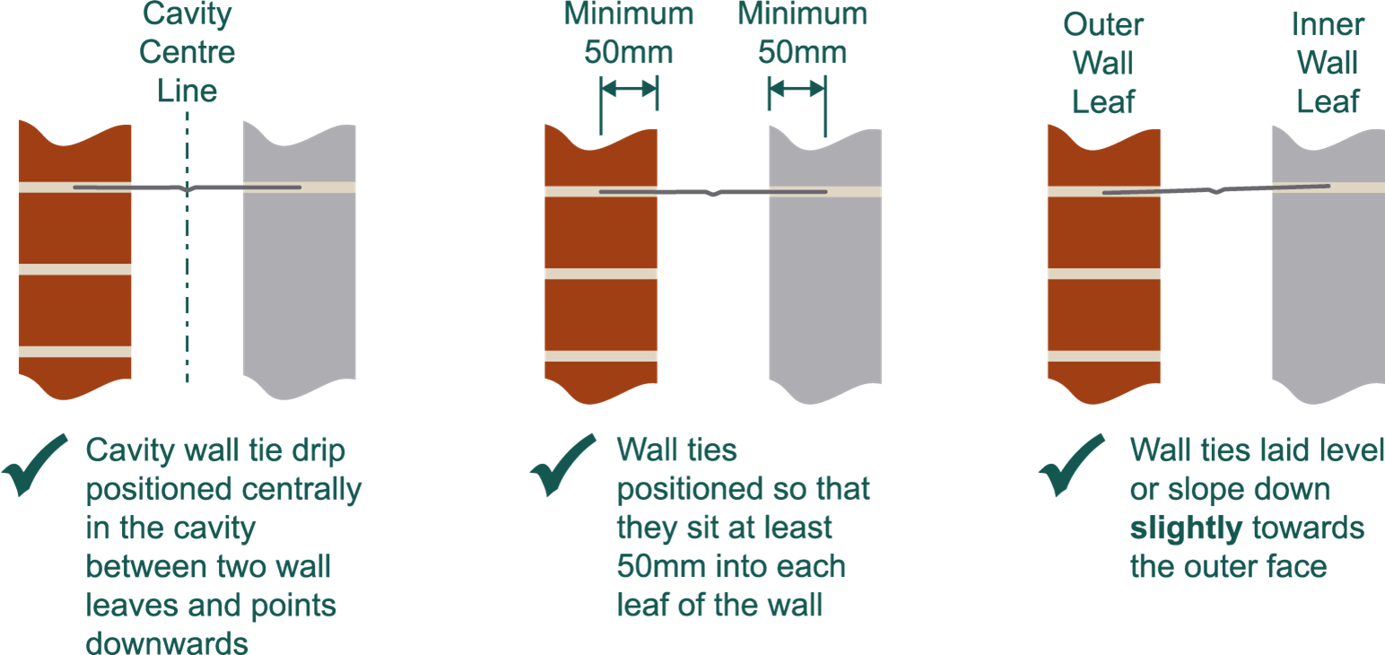
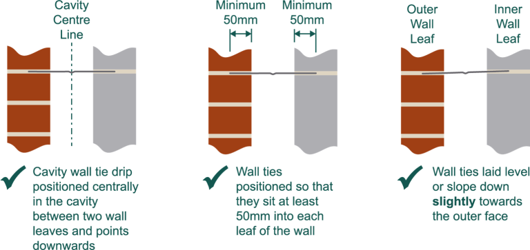
Wall ties should be installed by following the recommendations in Diagram 1 below so that:
- The drip is positioned centrally within the cavity, and it points downwards.
- They are laid level, or slope slightly downwards towards the outer leaf only. Do not allow the wall tie to slope towards the inner leaf.
- Positioned so that they sit at least 50mm into each masonry leaf, ensuring the minimum length is accommodated in accordance with Table 5 of Approved Document A . Some cavity wall ties require a larger embedment length, so it's important to undertake the installation in accordance with the manufacturer’s instructions or guidance (including any third-party accreditation), especially where they are a proprietary or a special product. It is always important to ensure that the wall ties are of a suitable length to follow this guidance relating to minimum length of embedment now that larger cavities are extensively being used onsite to accommodate additional insulation to meet the thermal requirements of Part L of the Building Regulations.
Diagram 1 : Correct wall tie installation methods
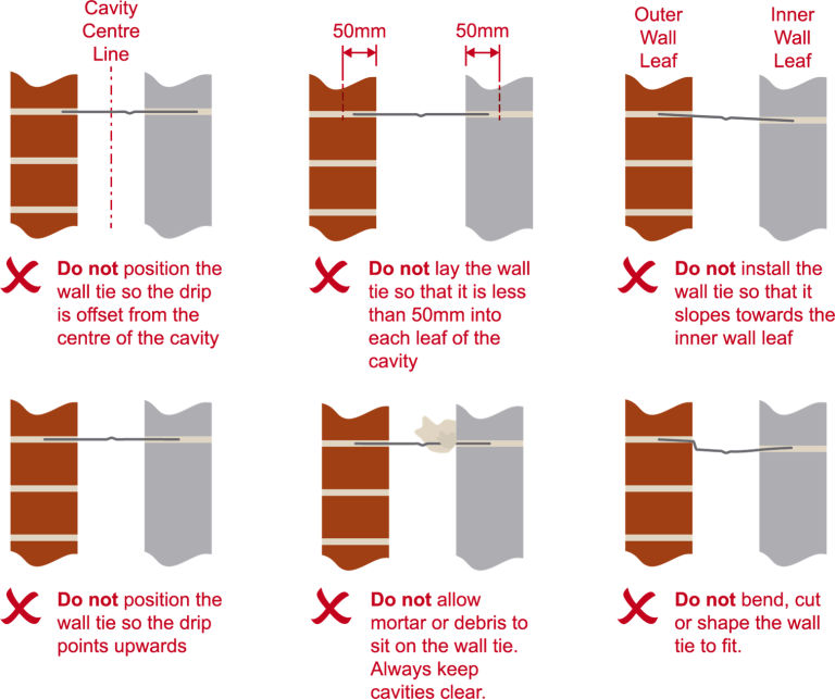
Diagram 2 (below) highlights some of the ways that cavity wall ties should not be installed:
- The drip should not be offset from the centre-line of the cavity unless allowed by manufacturers details.
- The wall tie should not sit into either leaf by less than 50mm.
- The wall tie should not slope towards the inner wall leaf.
- The drip should not point upwards unless allowed by the manufacturer’s details.
- Ensure the cavity is not bridged by any mortar or debris sitting on the cavity wall tie. Always keep cavities clear.
- Do not bend, cut, or shape the wall tie to fit the construction. Always refer to manufacturer’s details for permitted installation methods and adjustments.
Diagram 2: Incorrect wall tie installation methods
Spacing of ties
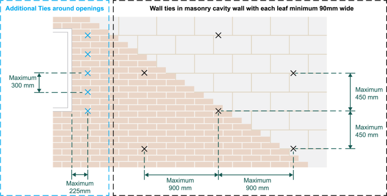
The approved design specification should always be followed. For masonry cavity walls with each leaf at least 90mm, Approved Document A and BS 8000-3 recommends that the wall ties should have a horizontal spacing of 900mm maximum and a vertical spacing of 450mm maximum as illustrated in Diagram 3. Alternatively, they can be spaced so that the number of wall ties per square metre is not less than 2.5 ties/m².
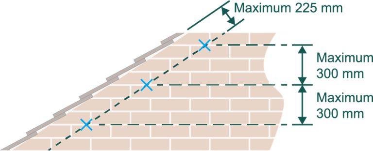
Wall ties should also be spaced not more than 300mm apart vertically and within 225mm from the vertical edges of all openings (Diagram 3), roof verges (Diagram 4) and movement joints.
Diagram 3: Wall tie spacing
Diagram 4: Wall tie spacing at gable roof verges
If in doubt, correct specification and installation should be checked with the designer or site manager, and further verified with the Local Authority Building Control team where changes from any approval are proposed.
Further details on cavity wall tie installation can be found in LABC Warranty Technical Manual.
Please Note: Every care was taken to ensure the information was correct at the time of publication. Any written guidance provided does not replace the user’s professional judgement. It is the responsibility of the dutyholder or person carrying out the work to ensure compliance with relevant building regulations or applicable technical standards.
This article was first published on 24 November 2022
Sign up to the building bulletin newsletter
Over 48,000 construction professionals have already signed up for the LABC Building Bulletin.
Join them and receive useful tips, practical technical information and industry news by email once every 6 weeks.
Subscribe to the Building Bulletin
Comments
Ychwanegu sylw newydd