Beware: Don’t just bolt your beams!
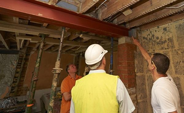
The traditional approach used when two steel beams are provided to support a cavity wall has been to design the beams to each carry half the total load and then connect them with pipe spacers and bolts, even when the loading to each beam was not equal.
This view has been challenged by many structural engineers who say you should not rely on spacers and bolts to fix them together. This becomes more important where the beams are likely to carry different loads, a typical situation in a cavity wall where the inner leaf carries the floor joists, resulting in significantly different loads on the inner and outer beams.
It is common for structural engineers to specify I-beams, also known as Universal Columns (UC), for situations described above. The horizontal elements in an I-beam are called “flanges”, and the vertical element is called the “web”.
I-beams are excellent at resisting vertical loading and bending as these are parallel to the web. However, I-beams are generally weaker in torsion, which may lead to twisting or deflection in the beam, particularly when unevenly loaded – this could result in cracking of masonry above, and in severe cases this could lead to failure of the beams.
So, steel beams and their connection details should always be designed by a competent structural engineer. Depending on the individual situation and the loadings involved, the structural engineer may specify one of several options to connect beams together and reduce torsion, such as:
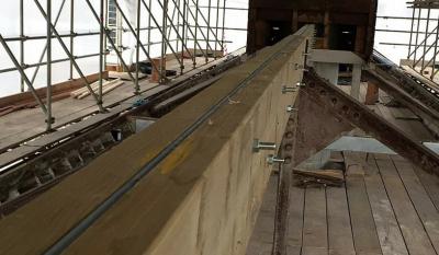
- using bolts and spacers at regular centres
- welding the beams together or providing a continuous welded plate over the top of both beams
- provide web stiffeners between the flanges of each beam
Ideally, onsite welding should be minimised where possible to reduce fire safety risks. If welding is unavoidable, it should be adequately planned and carried out in a safe manner by a competent person – and remember also to check if the client has a ‘hot works permit’ approval process in place before commencing.
Want to read more about traditional building techniques and structures?
Take a look at our articles from the "My dad told me about them!" series. Our most popular ones include:
- "My dad told me about them!": Flitch beams
- "My Dad told me about them!": Drain interceptor traps
- "My Dad told me about them!": Dragon ties
- "My Dad told me about them!": Lath and plaster ceilings
You might also find this article useful: Beware of point loads on beams.
Please Note: Every care was taken to ensure the information was correct at the time of publication. Any written guidance provided does not replace the user’s professional judgement. It is the responsibility of the dutyholder or person carrying out the work to ensure compliance with relevant building regulations or applicable technical standards.
This article was updated on 1 August 2022
Sign up to the building bulletin newsletter
Over 48,000 construction professionals have already signed up for the LABC Building Bulletin.
Join them and receive useful tips, practical technical information and industry news by email once every 6 weeks.
Subscribe to the Building Bulletin


Comments
Sense
Submitted 5 years 1 month ago
Beam Depth
Submitted 4 years 10 months ago
beam deflection
Submitted 4 years 7 months ago
Depends
Submitted 7 years 1 month ago
Pairs of beams
Submitted 7 years 1 month ago
Welded stiff plates between beams seem very excessive and difficult and time-consuming to install.
Pre-loading beams
Submitted 7 years 1 month ago
Then once the acrows are removed there is no cracking ...
How we design
Submitted 7 years 1 month ago
Example: Engineer has assumed load transfer between beams by way of pairs of bolts at 750 ctrs through web with spacers/lock nuts. To me that's no better than a single and provides no load transfer without significant bending or twisting occurring. Engineer has also assumed quarter point restraint via this bolted connection!!
203UB25 spanning 5.8m = big deflection
We always design as follows:
1. Unless wall above is 215mm solid we design the worst case beam.
2. Restraints are used where we have detailed it. So if we need restraint at third points we'll detail strapping to the structure (not to the adjacent beam, this is not adequate).
3. If we do tie the beams together, to restrain both back to the structure, then we detail top flange plates (welded to beam 1, bolted to beam 2, ie no insitu welding needed).
We try not to detail 203 UC due to weight issues, builder will end up splicing which creates it's own set of problems.
Asking a domestic builder to predeflect is not ideal, results will vary!!
1/4 point restraints (welded to beam 1 and bolted to beam 2)
Submitted 6 years 11 months ago
Reply
Submitted 6 years 11 months ago
If there is a query with the design of the connection, we suggest that you contact the engineer.
I'm sorry we can't be of further help on this one.
Regards,
Julie, LABC
Engineering by an engineer
Submitted 7 years 1 month ago
All fabricated steelwork should be completed by a ce-marking fabricator.
Add new comment